Choke Ring Ka-band TT&C Antenna
 Anywaves
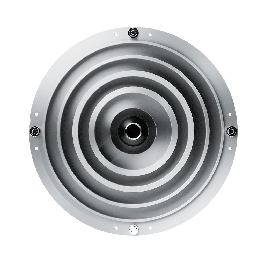
The Anywaves Ka-Band TT&C Antenna is a compact, reliable solution for telemetry, tracking and command operations in the Ka-band, available in Rx, Tx, and Rx/Tx models.
Typed specifications27 values
Discloses 7 of 10 fields engineers filter by in this category (category median 3).
- Frequency band
- Ka Tx 19.7–20.2 GHz, Rx 29.5–30 GHz · datasheet p.1
- Peak gain
- 5 dBi min · Rx model, realized gain @ boresight · datasheet p.2 3 dBi min · Tx model, realized gain @ boresight
- Mass
- 75 g max · Rx model · datasheet p.2 140 g max · Tx model
- Frequency range
- 29 500–30 000 MHz Rx model · datasheet p.2 19 700–20 200 MHz Tx model
- Beamwidth (-3 dB)
- 90 ° min · HPBW > 90° · datasheet p.1
- Envelope (L×W×H)
- L 108 x W 108 x H 44 mm datasheet p.2
- Polarization
- RHCP right or left hand circular, per model · datasheet p.2 dual circular single- or dual-circular polarization (RHCP/LHCP) | LHCP right or left hand circular, per model
- Antenna type
- other choke ring design · datasheet p.1
- TRL
- 7 product page
- Export status
- ITAR-free datasheet p.1
- RF connector
- 2.92 mm SMA 2.9 Female 50 · datasheet p.2
- Min gain over coverage
- 4 dBi min · Rx model, ±40° · datasheet p.2 -0.5 dBi min · Rx model, ±80° | 3 dBi min · Tx model, ±40° | 0 dBi min · Tx model, ±80°
- Axial ratio
- 5.5 dB max · Rx model, from 0° to ±40° · datasheet p.2 8.5 dB max · Rx model, from 0° to ±80° | 11 dB max · Rx model, from 0° to ±90° | 6 dB max · Tx model, from 0° to ±40° | 10.5 dB max · Tx model, from 0° to ±80° +1
- Mounting
- 4 x M3 (unthreaded hole) datasheet p.2
Each value is typed with its unit and measurement condition and cites the datasheet page it was taken from. Nothing is guessed: a field that is absent here has not been published by the manufacturer. machine-extracted ✓ checked by NewSpace Market ✓ manufacturer confirmed by the manufacturer.
As published by the supplier5 lines, in the manufacturer's own wording
- TRL
- 7
- Frequency band
- Rx: 29.5–30 GHz | Tx: 19.7–20.2 GHz
- Polarization
- Option 1 & 2: Left or Right Hand Circular Polarization (LHCP or RHCP) Option 3: LHCP in Rx and RHCP in Tx channels (or vice versa)
- Envelope size
- Option 1 : (Rx) 108 × 108 × 44 mm Option 2 : (Tx) 150 × 150 × 60 mm Option 3 : (Rx/Tx) 90 × 90 × 40 mm
- Realized gain
- Option 1: Rx: > 5 dBi @ boresight | > 0 dBi @ ±80° Option 2: Tx: > 3 dBi @ boresight | > 0 dBi @ ±80° Option 3: Rx/Tx: – Tx band: > 4 dBi @ boresight | > 0 dBi @ ±67° – Rx band: > 8 dBi @ boresight |
About
Engineered for Ka-Band reliability, this antenna features a choke ring design for minimal multipath interference and surface wave propagation, ensuring a clean, stable radiation pattern across full hemispherical coverage. Its full metal design, unlike radome-protected alternatives, provides inherent resistance to thermal extremes, radiation, and electrostatic discharges, with a qualification temperature range of −120°C to +120°C. The antenna is available as two distinct units—an Rx model (29.5–30 GHz, < 75 g) and a Tx model (19.7–20.2 GHz, < 140 g)—both fitting within a 1U CubeSat face. A full-duplex version (17.7–20.2 GHz and 27.5-30.0 GHz, 90°) with excellent axial ratio stability and a reflection coefficient better than −18 dB across the full frequency band. Supporting single or dual-circular polarization (RHCP/LHCP), scalable in frequency, and compatible with the Anywaves Test Hat, it offers the flexibility required by modern satellite platforms. Lightweight, ITAR Free, and supplied with full acceptance testing on flight models.
Documentation
Need the full ICD, test reports or a specific revision? Ask the supplier directly.