High Gain X-Band Payload Telemetry Antenna
 Anywaves
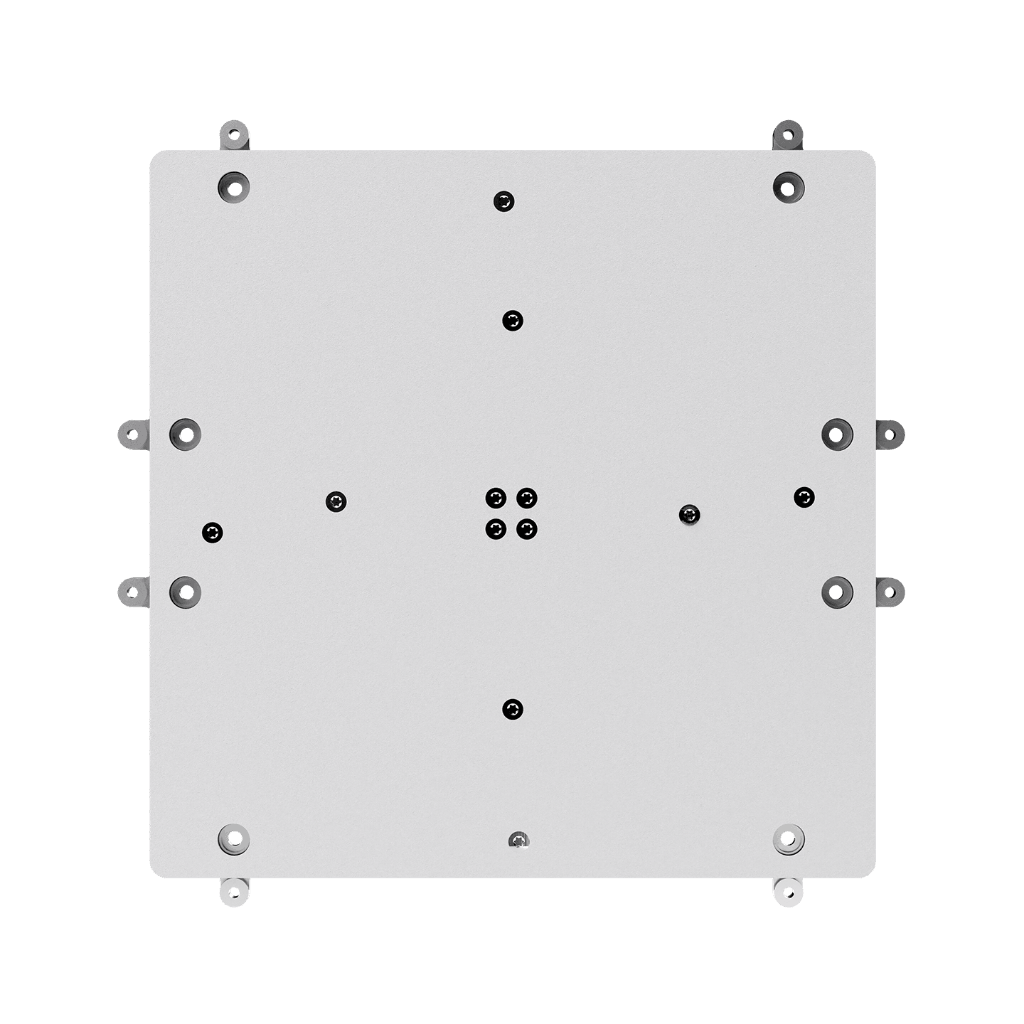
The Anywaves High Gain X-Band Antenna delivers more than 20 dBi of realized gain at 8.2 GHz, enabling maximum data throughput for Earth observation and remote sensing missions.
Typed specifications16 values
Discloses 6 of 10 fields engineers filter by in this category (category median 3).
- Frequency band
- X Tx · datasheet p.1
- Peak gain
- 20 dBi min · realized gain @ boresight, @8.2 GHz · datasheet p.2
- Mass
- 503 g product page
- Frequency range
- 7 900–8 500 MHz Tx · datasheet p.2
- Beamwidth (-3 dB)
- 9 ° HPBW ~9° (±4.5° in all planes) · datasheet p.2
- Envelope (L×W×H)
- L 200 x W 200 x H 16 mm (without connector); protruding height <8 mm datasheet p.2
- Polarization
- RHCP right or left hand circular polarization · datasheet p.2 LHCP right or left hand circular polarization
- TRL
- 5 product page
- Export status
- ITAR-free datasheet p.1
- RF connector
- SMA datasheet p.2
- Connector
- 503 g ± 20% product page
- Axial ratio
- 1 dB max · 8.2 GHz, from 0° to ± 7.5° (all planes) · datasheet p.2 2 dB max · 8.2 GHz, from 0° to ± 8° (all planes)
- Max RF power
- 20 W either 1x20 W or 2x10 W continuous wave · datasheet p.2
- Mounting
- 4 x M3 (unthreaded hole) datasheet p.2
Each value is typed with its unit and measurement condition and cites the datasheet page it was taken from. Nothing is guessed: a field that is absent here has not been published by the manufacturer. machine-extracted ✓ checked by NewSpace Market ✓ manufacturer confirmed by the manufacturer.
As published by the supplier8 lines, in the manufacturer's own wording
- Realized Gain
- > 20 dBi
- Configuration options
- LHCP, RHCP
- Frequency band
- 7.9 GHz to 8.5 GHz
- Polarization
- Left or Right Hand Circular Polarization
- Envelope size without connector
- L 200 × W 200 × H 16 mm
- Realized gain (2)
- > 20 dBi @ boresight @ 8.2 GHz
- TRL
- 5
- Mass with connector
- 503 g ± 20%
About
The High Gain X-Band Antenna delivers a realized gain exceeding 20 dBi at 8.2 GHz, achieved through a large 200 × 200 mm aperture that concentrates RF energy into a narrow 9° pencil beam. This level of gain translates directly into a significantly improved link budget and higher achievable data rates, making it ideal for Earth observation or remote sensing missions with demanding payload downlink requirements. The antenna’s Half Power Beam Width of approximately 9° produces a highly directive pencil beam that maximises radiated power towards the ground station during the downlink window. The axial ratio stays below 1 dB within ±5° of boresight, ensuring excellent circular polarization purity and minimising losses due to Faraday rotation. Featuring only a 200 × 200 mm aperture, the High Gain X-Band Antenna maintains a total height of only 16 mm, with less than 8 mm of protrusion above the satellite panel. Protected by a PEEK radome with SG121FD white paint on flight models, it withstands thermal extremes from −120°C to +120°C and prevents electrostatic discharge events. The antenna operates from 7.9 to 8.5 GHz (600 MHz bandwidth) in LHCP or RHCP, with a reflection coefficient better than −18 dB and an axial ratio below 1 dB at ±5°. It is compatible with the Anywaves Test Hat for X-Band Antennas and is ITAR Free.
Documentation
Need the full ICD, test reports or a specific revision? Ask the supplier directly.