CubeSat Kit™ Cover Plate Assembly
 Pumpkin, Inc.
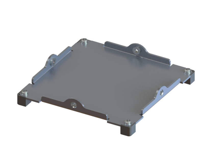
A precision aluminum end-plate assembly that forms the payload end of a CubeSat Kit structure, secured to the Chassis Walls and fitted with four corner feet per the CubeSat Design Specification.
Typed specifications7 values
Discloses 1 of 8 fields engineers filter by in this category (category median 1).
- Material (as printed)
- Al 5052-H32, plated per CubeSat Design Specification (CDS) product page
- Envelope (L×W×H)
- 100 mm x 100 mm / 3.937 in x 3.937 in product page 100 x 100 3.937 x 3.937 in
- Structure type
- panel or bracket CubeSat Kit cover plate · datasheet p.1
- Form factor
- 1U Pumpkin 1U Chassis · datasheet p.1
- Satellite class
- CubeSat datasheet p.1
- Deployment (kill) switches
- 4 quad switch; one switch tab must be removed for Pumpkin CubeS… · datasheet p.1
Each value is typed with its unit and measurement condition and cites the datasheet page it was taken from. Nothing is guessed: a field that is absent here has not been published by the manufacturer. machine-extracted ✓ checked by NewSpace Market ✓ manufacturer confirmed by the manufacturer.
As published by the supplier10 lines, in the manufacturer's own wording
- Configuration option: type
- Solid-Wall, Skeletonized
- Material
- Al 5052-H32, plated per CubeSat Design Specification (CDS)
- Mounting fasteners
- 4x M3 flathead stainless-steel screws
- Corner feet
- 4 (included)
- Options
- Separation plungers in feet; additional separation switches in feet
- Price range (USD)
- $495.00
- Dimensions
- 100 mm x 100 mm / 3.937 in x 3.937 in
- Switch travel (open to closed)
- 1.75 mm
- Maximum allowable stroke (open to overtravel)
- 2.55 mm
- Switch actuation force
- 0.4 N
About
The Cover Plate Assembly forms the end of a CubeSat Kit™ structure opposite the Base Plate Assembly — typically the payload end. It is precision constructed from Al 5052-H32 and plated according to the CubeSat Design Specification (CDS), the industry standard governing nanosatellite structural interfaces.
Each Cover Plate Assembly is secured to the Chassis Walls via four M3 flathead stainless-steel screws, and includes four corner feet to satisfy CDS rail/foot requirements for deployment from a P-POD-class deployer. The assembly is offered in Solid-Wall and Skeletonized configurations, matching the corresponding Chassis Walls type.
Options include separation plungers integrated into the feet (used to indicate deployment/separation from the dispenser rails) and additional separation switches mounted in the feet, allowing the satellite to sense physical separation from its deployer. As flight hardware, it is flight qualified and space proven, having been used across Pumpkin’s CubeSat Kit flight heritage.
Documentation
Need the full ICD, test reports or a specific revision? Ask the supplier directly.