High-power Multi-channel Electrical Power System Module (EPSM1)
 Pumpkin, Inc.
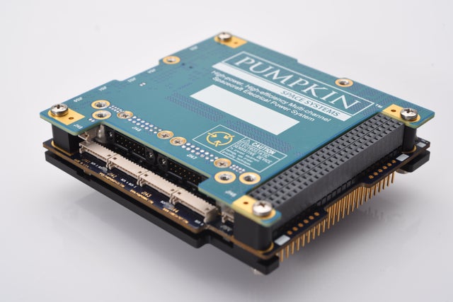
A high-performance, highly efficient FPGA-driven, GaNFET-based multichannel power system module for small satellites, handling up to 480W of solar input and ~300W of regulated output power.
Typed specifications104 values
Discloses 11 of 14 fields engineers filter by in this category (category median 7).
- Mass
- 230 g typ, aluminum standoffs, no heat spreader · datasheet p.7 300 g max · SWaP: < 300g
- Total output power
- 480 W product page
- Conversion efficiency
- 97.5 % minimum block efficiency over a wide range of operating currents · datasheet p.3 96 % min · GaNFET switching | 97.5 % min · minimum efficiency of each block over a wide range of operati… | 98.5 % max · 96-98.5% efficient 250kHz GaNFET switching
- Envelope (L×W×H)
- 96 x 90 x 15.24 mm length x width x height · datasheet p.7
- Outputs (as printed)
- 3 regulated outputs (3.3/5.0/12V, 5-8A); 1 switchable regulated output (4-28V, 8A) datasheet p.1 4-28V, 8A (switchable)
- Supply voltage
- 8-28V (solar array inputs) datasheet p.1 8 V min · Solar array input, normal operating conditions | 28 V max · Solar array input, normal operating conditions | 16.8V (battery blocks)
- Power consumption
- 2 W Operating power consumption, nominal · datasheet p.9 480 W | 2 W Operating power consumption, no commands or telemetry active … | 2 W operating power consumption, typ: deployment switches not inh… | 3 W max · SWaP: < 3W
- Data interface
- I2C SCPI over I2C via SupMCU, clock speed up to 400 kHz, default … · datasheet p.6
- Operating temperature
- -40 °C min · datasheet p.7 85 °C max | -40–85 °C absolute maximum ratings
- Unit type
- EPS without battery intended for use with zero, one or two dedicated external bat… · datasheet p.3
- Board format
- CubeSat Kit bus datasheet p.3
- Bus and outputs type
- hybrid (regulated rails + battery bus) regulated 3.3/5/12 V and AUX outputs; BAT1 unregulated batter… · datasheet p.5
- Unregulated (battery) bus voltage
- 32 V internal unregulated power ring topology; ring voltage availa… · datasheet p.1
- Regulated output voltages
- 28 V nom. · AUX output block, nominally +28Vdc, reconfigurable to a lower… · datasheet p.3 16.4 V 4SNP, Li-Ion, CC/CV, Float voltage | 16.4 V Battery charging voltage | 3.3 V regulated output block | 4 V min · AUX block output +5
- Switchable outputs
- 1 switchable regulated output (AUX) with ON/OFF control, 4-28V, 8A · datasheet p.1
- Solar array inputs
- 6 SAI1-SAI6, each with MPPT · datasheet p.1
- Solar input voltage window
- 8 V min · Input to MPPT-equipped block; SAI1-SAI6; normal operating con… · datasheet p.9 -0.3 V min · on any SAI POS input | 28 V max · Input to MPPT-equipped block; SAI1-SAI6; normal operating con… | 55 V max · on any SAI POS input | 8–28 V input to MPPT-equipped block, SAI1-SAI6, normal operating con…
- Max solar input power
- 2.7 W buck / down mode, at 10V · datasheet p.9 6 W buck / down mode, at 15V | 10 W buck / down mode, at 20V | 16.9 W buck / down mode, at 25V | 24.3 W buck / down mode, at 30V +10
- Solar array regulation
- MPPT kHz-speed perturb-and-observe agile MPPT algorithm on each so… · datasheet p.1
- Protections
- over-temperature 2 programmable overtemperature (OT) limits, OT1 & OT2 · datasheet p.1 watchdog configurable watchdog timer (WDT) | over-voltage input overvoltage shunt on solar array inputs, turn-on voltag… | over-current (LCL) programmable current limit per block, protected against overc… | over-current (LCL) +1
- Connector
- 104-pin CubeSat Kit bus connector; solar array inputs on 10-pin connectors J141-J144 (mating Hirose DF13-10S-1.25C); battery blocks on two 14-pin connectors J147 & J148 datasheet p.11
- Random vibration
- 14 g RMS tested to NASA GEVS levels · datasheet p.1
- Satellite class
- CubeSat CubeSats & nanosatellites; Pumpkin MISC 3 CubeSats · datasheet p.1 nanosat 1-10 kg CubeSats & nanosatellites; Pumpkin SUPERNOVA NanoSats
- Max current per output
- 8 A 12V, AUX · datasheet p.4 5 A 3.3V, 5V | 2 A per solar array input | 5 A Regulated output | 8.4 A max · 12V block (includes current from 5V & 3.3V blocks), absolute … +14
- Battery voltage range accepted
- 16.8 V Battery (nominal) · datasheet p.1 16.8 V only 16.8V 4S2P Li-Ion batteries supported; absolute maximum … | -0.3 V min · on any BAT V+ input | 16.8 V max · on any BAT V+ input | 16.4 V nom. · battery charging voltage, typ
- Max battery charge current
- 8 A datasheet p.1 6 A 4SNP, Li-Ion, CC/CV, Initial CC current | 6 A 4SNP, Li-Ion, CC/CV, Max CC current | 8 A max · battery current, charging (-10 to -8000 mA)
- MPPT
- yes datasheet p.1
- Max solar input current
- 2 A max · input to MPPT-equipped block, SAI1-SAI4 · datasheet p.9 4 A max · input to MPPT-equipped block, SAI5-SAI6
- Integrated battery cell configuration
- 4S2P only 16.8V 4S2P Li-Ion batteries supported (external battery) · datasheet p.5
- Inhibit / RBF inputs
- 3 three independent system-level inhibits: RBF (J145), Sep 1 (J… · datasheet p.20
- Housekeeping telemetry
- Fully formatted telemetry via SupMCU: comprehensive voltage, current and temperature information on the blocks and overall system status; 8 LMx35-type temperature telemetry channels; radiation dosimeter datasheet p.1
Each value is typed with its unit and measurement condition and cites the datasheet page it was taken from. Nothing is guessed: a field that is absent here has not been published by the manufacturer. machine-extracted ✓ checked by NewSpace Market ✓ manufacturer confirmed by the manufacturer.
As published by the supplier12 lines, in the manufacturer's own wording
- Switching blocks
- Twelve non-isolated 250 kHz switching blocks
- Solar array inputs (sai1-sai6) max total power
- 480 W
- Battery reserve power
- up to 112 W per battery
- Battery charge voltage
- 16.8 V Li-Ion, CC/CV, up to 6 A
- Output 3v3 / 5v0 current
- up to 5 A each
- Output 12v / 28v current
- up to 8 A each
- Total regulated output power
- ~300 W
- Efficiency
- >99% typical at moderate-to-high currents
- Temperature sensors
- 3 internal, 8 external ports
- Telemetry/telecommand interface
- SCPI over I2C via Pumpkin SupMCU
- Sai max voltage/current (SAI1-SAI4)
- 28 V, 2 A
- Sai max voltage/current (SAI5 & SAI6)
- 28 V, 4 A
About
The EPSM 1 serves as the nexus of a complete, high-performance and highly efficient FPGA-driven, GaNFET-based multichannel power system for small satellites. Its advanced functionality takes the guesswork out of managing high and varying power levels in small satellites. The EPSM 1’s power-handling circuitry is comprised of twelve non-isolated 250kHz switching blocks divided into three groups under FPGA and MCU control: the solar array inputs (SAI1-SAI6), the batteries (BAT1 & BAT2), and the outputs (3V3, 5V0, 12V & 28V).
The six SAI blocks collect power for the outputs and for battery charging as required. Each SAI block independently implements a kHz-speed perturb-and-observe MPPT algorithm, with programmable maximum current setpoints and automatic power equalization across all six SAIs. The SAI blocks can handle up to 480W total solar input power. Each independent battery block provides reserve power (up to 112W per battery) when output loads exceed the total SAI input power. The EPSM 1 charges each connected 16.8V Li-Ion battery in CC/CV modes at up to 6A, with automatic CHG/DSG switchover; the recommended battery is Pumpkin’s BM 2 4S2P battery module (not included), and the EPSM 1 is compatible with the BM 2’s battery balancing, heaters, and all telecommands and telemetry.
Each output block provides a regulated output voltage at up to 5A (3V3 & 5V0) and 8A (12V & 28V), for a total of ~300W. Each output block has a programmable current limit, and the 28V block is switchable and can operate at lower voltages. A Pumpkin SupMCU handles telecommands and telemetry via SCPI over I2C, and implements sophisticated additional features including a programmable WDT, programmable overtemperature limits OT1 & OT2, smart RBF and separation inhibits, automatic recovery from power deficit conditions and automatic recovery from solar panel shading. All telemetry is timestamped and fully formatted in engineering units. The EPSM 1 is provided with an integrated heat spreader and a built-in overvoltage clamp, and operates within substantially derated operating conditions. Three internal and eight external temperature sensor ports are provided. The FPGA is SEU immune, and multiple EPSM 1s can be paralleled together. Per-block efficiency is typically >99% at moderate-to-high currents.
Includes an EPSM1 module (with one of three H1/H2 connector options: none, stackthrough or non-stackthrough), a Development Board 2 with EPSM1 installed, a Load Board B, four SAI harnesses, RBF and Separation inhibit harnesses, a USB Debug Adapter with flex/USB cables, and downloadable Windows-based and Python-based GUIs. Does not include batteries, solar panels, external power sources, or flying-lead battery harnesses (can be ordered separately). Compatible with all CubeSat architectures that employ the 104-pin connector, solar cell strings up to 28V and 2A (SAI1-SAI4) / 4A (SAI5 & SAI6), 16.8V batteries chargeable via CC/CV scheme, and Pumpkin’s SUPERNOVA Remote GSIM.
Documentation
Need the full ICD, test reports or a specific revision? Ask the supplier directly.