Payload Data Handling System VPDHS
 VECTRONIC Aerospace GmbH
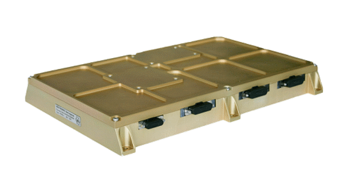
The VPDHS is a Payload Data Handling System developed by VECTRONIC Aerospace for small satellite applications, designed to receive, store, compress, and format payload data for transmission to ground stations.
Typed specifications34 values
Discloses 6 of 14 fields engineers filter by in this category (category median 5).
- Mass
- 2 300 g datasheet p.1
- Envelope (L×W×H)
- 290 mm x 192 mm x 34 mm datasheet p.1 290 mm x 192 mm x 34 mm mounting pattern 6x M4
- RAM
- 4 096 MB datasheet p.1 4 096 MB SDRAM storage capacity
- Mass storage
- 16 GB datasheet p.1 16 GB non-volatile Flash storage capacity
- Supply voltage
- 9–18 V datasheet p.1 18–36 V
- Power consumption
- 15 W Max · datasheet p.1 15 W max
- Data interface
- RS-422 datasheet p.1 other 24 SerDes inputs @ up to 2 Gbps | LVDS 30 LVDS I/O @ 480 Mbps, 1 LVDS output @ 105 Mbps (e.g. Camera… | RS-422 signal interface RS422 / RS485, serial asynchronous | RS-485 +2
- Operating temperature
- -20–70 °C datasheet p.1
- Radiation tolerance (TID)
- 10 krad datasheet p.1 10 krad min · >10 kRad
- Radiation and fault mitigation
- FPGA bitstream scrubbing datasheet p.1 other SEU-Protection of the FPGA bit configuration with a SEU-Contr… | current and upset monitoring System Monitor supervises internal temperatures and internal …
- Connector
- MDM-25 datasheet p.1
- Survival temperature
- -40–80 °C datasheet p.1 -40–80 °C storage temp. range
- Random vibration
- 13.4 g RMS datasheet p.1
- Satellite class
- smallsat 100-500 kg datasheet p.1
- FPGA
- FPGA/Microcontroller architecture; Microcontroller acts as System Monitor supervising the FPGA, internal temperatures and internal current consumption datasheet p.1
- RAM type
- SDRAM datasheet p.1
- Data interface speed
- 105 Mbps 1 LVDS output · datasheet p.1 480 Mbps 30 LVDS I/O | 2 000 Mbps max · 24 SerDes inputs, up to
Each value is typed with its unit and measurement condition and cites the datasheet page it was taken from. Nothing is guessed: a field that is absent here has not been published by the manufacturer. machine-extracted ✓ checked by NewSpace Market ✓ manufacturer confirmed by the manufacturer.
As published by the supplier16 lines, in the manufacturer's own wording
- Dimensions
- 290 mm x 192 mm x 34 mm
- Mass
- 2.3 kg
- Mounting pattern
- 6 x M4
- Power consumption
- Max 15 W
- Power supply
- 9 V – 18 V, 18 V – 36 V
- Signal interface
- RS422 / RS485
- Signal characteristics
- Serial asynchronous
- Connector type
- MDM-25
- Operating temp.range
- -20°C to + 70°C
- Storage temp. range
- -40°C to + 80°C
- Vibration
- 13.4 g rms
- Radiation tolerance
- > 20 krad
- Storage capacity sdram
- 4 GBytes
- Storage capacity flash
- 16 GBytes non-volatile
- Data interface
- 30 LVDS I/O @ 480 Mbps 24 SerDes inputs @ up to 2 Gbps 1 LVDS output @ 105 Mbps
- Other inputs
- Pulse-per-second synchronization
About
The VECTRONIC Aerospace Payload Data Handling System (VPDHS) is engineered for small satellite applications, focusing on efficient management of payload data, particularly from cameras. Its primary functions include receiving high-speed payload data, storing it, compressing it, and formatting it for transmission via a High Speed Interface to a ground station. The system is built on an FPGA/Microcontroller-Architecture, offering 4 GBytes of SDRAM and 16 GBytes of non-volatile Flash memory for data storage. The microcontroller serves as the System Monitor, managing the proper operation of the FPGA, monitoring internal temperatures and current consumption, and ensuring the integrity of the in-circuit programmable Flash memory content. Key tasks of the VPDHS include reception of high-speed data from two cameras via LVDS interfaces (e.g., Camera Link), optional storage in non-volatile flash memory, and an RS422 interface to the On-Board Attitude Control computer for ACS data. It also provides multiple LVDS interfaces to other on-board devices, an RS422 interface to a GPS Receiver for pulse-per-second synchronization, real-time adjustable lossy and lossless compression of imager data, CCSDS formatting for transmitted data, and a High Speed Interface to the On-Board transmitter. The FPGA bit configuration is protected against Single Event Upsets (SEU) by a SEU-Controller, managed by the System Monitor.
Documentation
Need the full ICD, test reports or a specific revision? Ask the supplier directly.